Tomography tutorial (EMPIAR-10164)
This tutorial shows how to convert raw tilt-series from EMPIAR-10164 into a ~3A resolution structure of immature HIV-1 Gag protein.
Total running time required to complete this tutorial: ~20 hrs.
Pre-calculated results are available in the demo instance of nextPYP.
We first use the command line to download and decompress a .tbz file containing a subset of 5 tilt-series (down-sampled 2x compared to the original super-resolution data):
# cd to a location in the shared file system and run:

wget https://nextpyp.app/files/data/nextpyp_tomo_tutorial.tbz
tar xvfz nextpyp_tomo_tutorial.tbz
After this, you should have 41 tilt movies in .tif format for each of the tilt-series (TS_01, TS_03, TS_43, TS_45, and TS_54), an initial reference, and a shape mask
Open your browser and navigate to the url of your nextPYP instance (e.g., https://nextpyp.myorganization.org).
Step 1: Create a new project
Data processing runs are organized into projects. We will create a new project for this tutorial
The first time you login into
nextPYP, you should see an empty Dashboard:
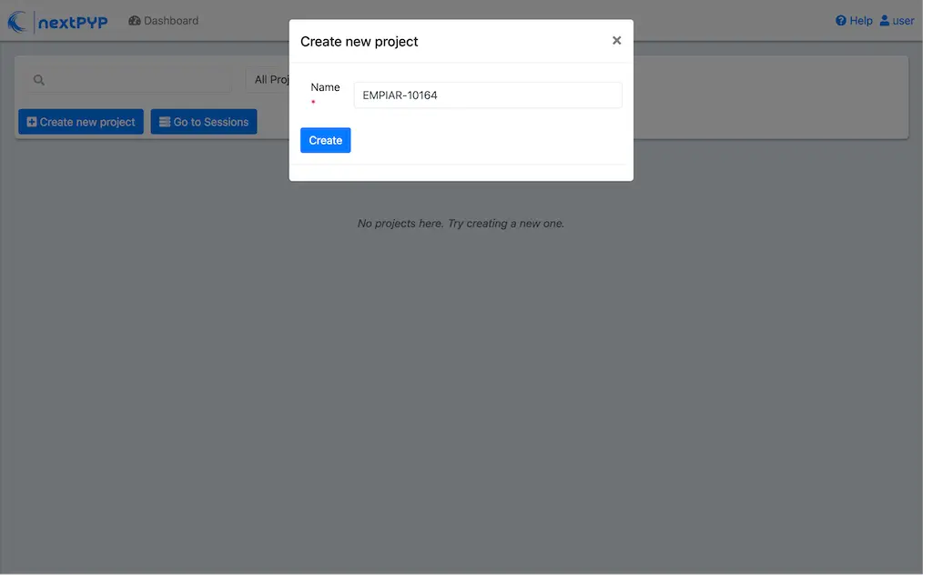
Click on Create new project, give the project a name, and select Create
Select the new project from the Dashboard and click Open
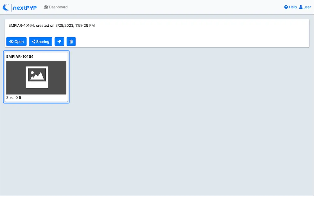
The newly created project will be empty and a Jobs panel will appear on the right

Step 2: Import raw tilt-series
Import the raw tilt-series downloaded above ( <1 min)
Go to Import Data and select Tomography (from Raw Data)

A form to enter parameters will appear:
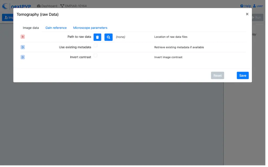
Go to the Raw data tab:
Set the
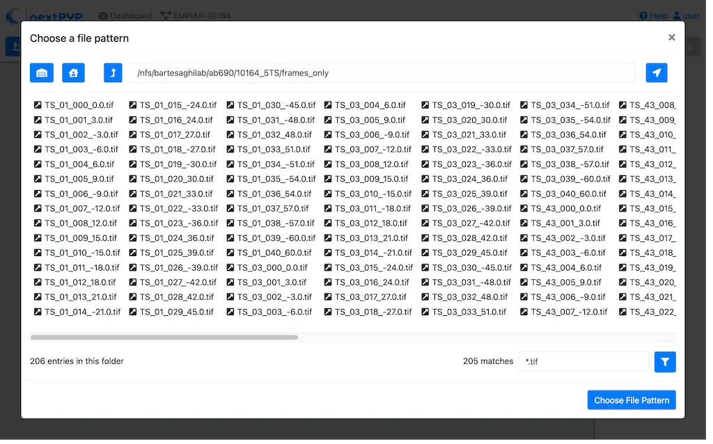
Locationof the raw data by clicking on the icon and browsing to the directory where the you downloaded the raw movie framesType
TS_*.tifin the filter box (lower right) and click on the icon to verify your selection. 205 matches should be displayedClick Choose File Pattern to save your selection
Click on the Microscope parameters tab
Set
Pixel size (A)to 1.35Set
Acceleration voltage (kV)to 300Set
Tilt-axis angle (degrees)to 85.3

Click Save and the new block will appear on the project page
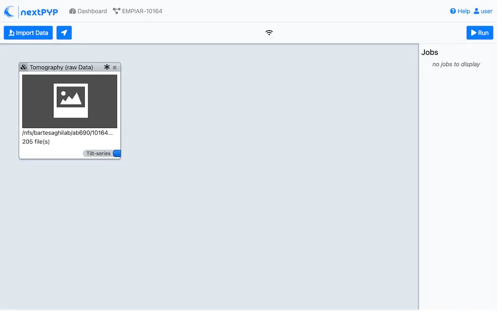
The block is in the modified state (indicated by the sign) and is ready to be executed
Clicking the button Run will show another dialog where you can select which blocks to run:
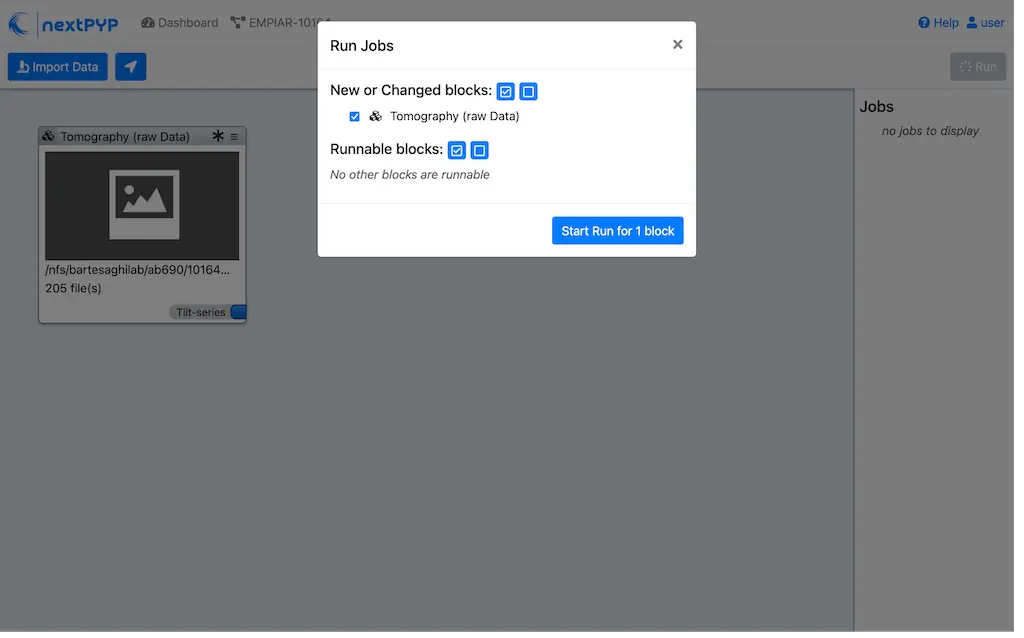
Since there is only one block available, simply click on Start Run for 1 block. This will launch a process that reads one tilt at random and displays the resulting image inside the block

Click on the thumbnail inside the block to see a larger version of the projection image
Step 3: Pre-processing
Motion correction, CTF estimation, tilt-series alignment and reconstruction ( 5 min)
Click on
Tilt-series(output of the Tomography (from Raw Data) block) and select Pre-processing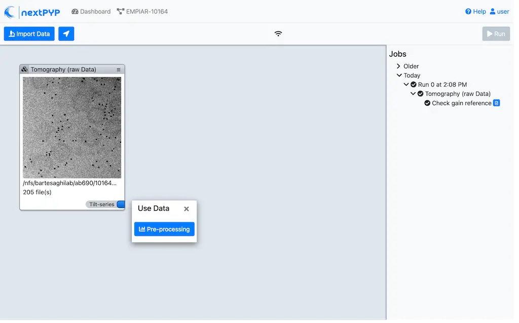
Go to the Frame alignment tab:
Leave
Frame patternas the default value TILTSERIES_SCANORD_ANGLE.tif.nextPYPuses this to extract the metadata from the file names, for example,TS_54_037_57.0.tifwould indicate that the tilt-series name isTS_54, the exposure acquistion order is37, and the corresponding tilt-angle is57.0degreesClick on the CTF determination tab
Set
Max resolution (A)to 5. This will be the maximum resolution used to determine the CTF parameters for each tilt-seriesClick on the Resources tab
Set
Split, Threadsto 11. This tellsnextPYPto use 11 threads to process each tilt-seriesSet other runtime parameters as needed (see Computing resources)
Click Save, Run, and Start Run for 1 block. Follow the status of the run in the Jobs panel
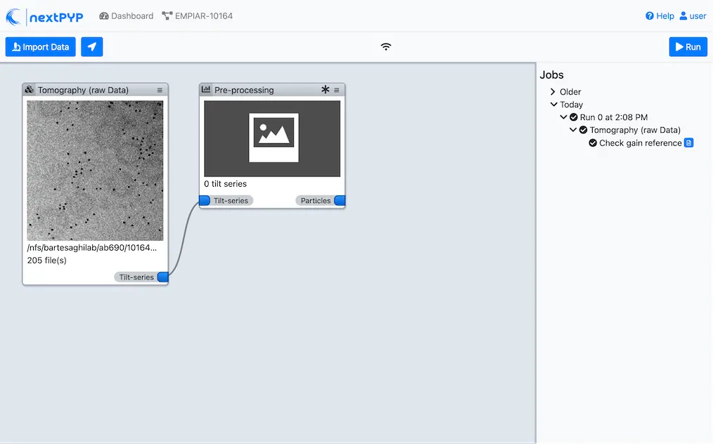
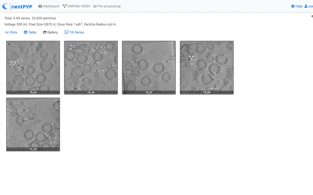
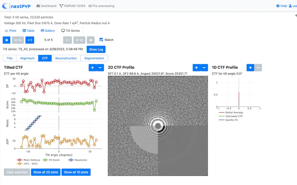
Click inside the Pre-processing block to inspect the results (you don’t need to wait until processing is done to do this). Results will be grouped into tabs:
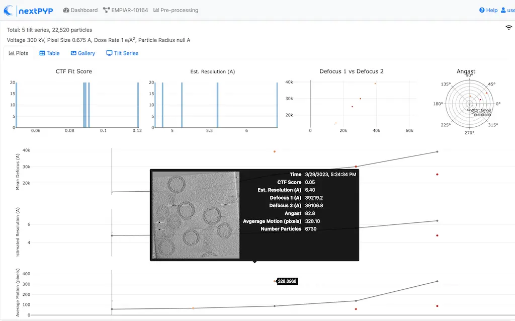

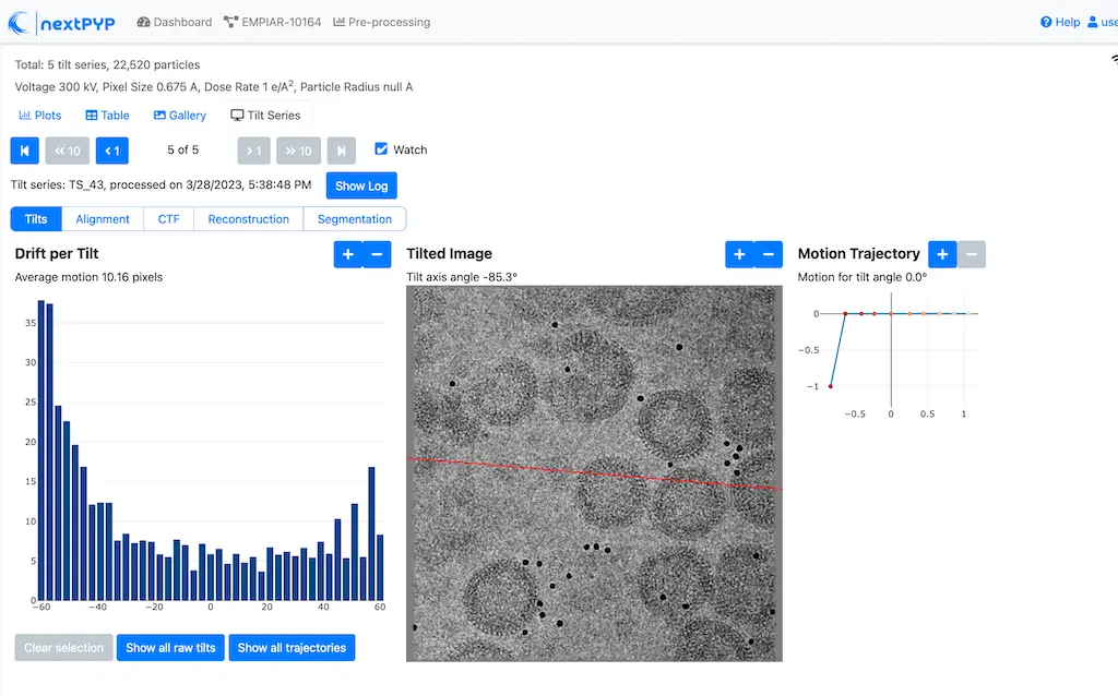

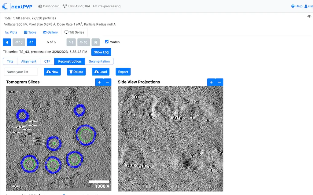
Tip
While on the Tilt Series tab, use the navigation bar at the top of the page to look at the results for other tilt-series
Step 4: Virion selection
Selection of virion centers ( 1 min)
Click on
Tomograms(output of the Pre-processing block) and select Particle pickingGo to the Particle detection tab:
Set
Detection methodto virionsSet
Virion radius (A)to 500
Click Save, Run, and Start Run for 1 block. Follow the status of the run in the Jobs panel
Step 5: Virion segmentation
Segment individual virions in 3D ( 1 min)
Click on
Particles(output of the Particle picking block) and select Segmentation (min-flow/max-cut)Click Save, Run, and Start Run for 1 block. Follow the status of the run in the Jobs panel
This next step is optional, but it showcases tools available in nextPYP to work with virions:
Go inside the Segmentation (min-flow/max-cut) block and click on the Segmentation tab
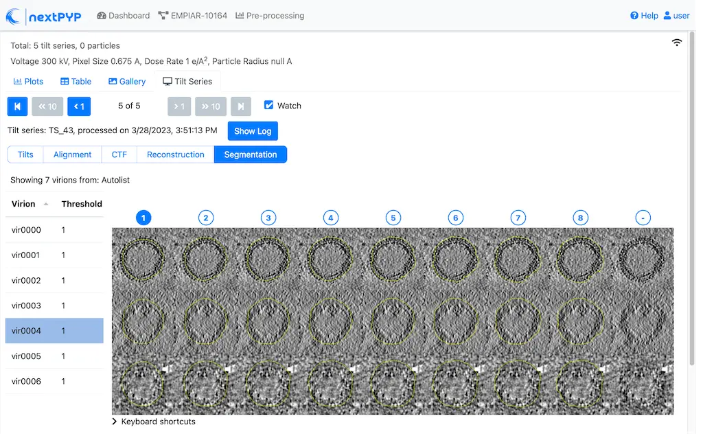
Select a virion from the table to show its 3D segmentation (8 different thresholds are shown as yellow contours in columns 1-8). The column number highlighted in blue represents the selected threshold value (default is 1, click on a different column to select a better threshold). The best threshold is the one that more closely follows the outermost membrane layer. If none of the columns look reasonable (or if you want to ignore the current virion), select the last column (“-“)
Repeat this process for all virions in the table and all tilt-series in the dataset
Tip
Click on > Keyboard shortcuts (under the virion image) to reveal instructions on how to speed up the threshold selection process
Step 6: Particle picking
Select particles from the surface of virions ( 3 min)
Click on
Segmentation (min-cut/max-flow)(output of the Segmentation (min-flow/max-cut) block) and select Particle picking (closed surfaces)Go to the Particle detection tab:
Set
Particle radius (A)to 50Set
Detection methodto uniform. This will select uniformaly distributed particles on the virion surfacesSet
Minimum distance between particles (voxels)to 8Set
Size of equatorial band to restrict search (A)to 800. Given that the virions are 1000 A in diameter, this setting limits the search to 80% of the surface area, avoiding particle selection from the top and bottom regions of the virions where the missing wedge effects are more pronounced
Click Save, Run, and Start Run for 1 block. Follow the status of the run in the Jobs panel
Navigate to the Particles tab to inspect the particle coordinates:

Step 7: Reference-based refinement
Constrained reference-based particle alignment ( 8 hr)
Click on
Particles(output of the Particle picking (closed surfaces) block) and select Reference-based refinementGo to the Sample tab:
Set
Molecular weight (kDa)to 300. This value is used by cisTEM to estimate the volume occupied by the particle, based on a conversion factor of 810 Da/nm^3. The estimated volume is used to calculate the spectral signal-to-noise ratio (SSNR), which in turn is used to apply an optimal filter to enhance the reconstructionSet
Particle radius (A)to 150Set
Symmetryto C6Click on the Particle extraction tab
Set
Box size (pixels)to 192Set
Image binningto 2. Particles will be extracted at 2x binning, as only low-resolution information is needed at this stageClick on the Particle scoring function tab
Set
Last tilt for refinementto 10. This will use the first eleven tilts for refinement (numbering is 0-based)Set
Max resolution (A)to 8.0Click on the Reference-based refinement tab
Specify the location of the
Initial model (*.mrc)by clicking on the icon , navigating to the folder where you downloaded the data for the tutorial, and selecting the file EMPIAR-10164_init_ref.mrcSet
Particle rotation Psi range (degrees)andParticle rotation Theta range (degrees)to 10. This setting restricts the out-of-plane rotation of particles during refinement to a maximum of 10 degreesSet
Particle rotation step (degrees)to 2Set
Particle translation range (A)to 50Set
Particle translation step (A)to 6Click on the Reconstruction tab
Check
Show advanced optionsSet
Max tilt-angleto 50Set
Min tilt-angleto -50Click on the Resources tab
Set
Split, Threadsto the maximum allowable by your system. Since this dataset has thousands of particles per tilt-series, this will allow for a faster processing time.Set
Merge, Threadsto 6. This will use 6 threads to merge the intermediate results from each tilt-series. Since this is not a CPU-intensive task, using higher values may not be beneficial
Save your changes, click Run and Start Run for 1 block
One round of refinement and reconstruction will be executed. Click inside the block to see the results
Step 8. 3D refinement
Tilt-geometry parameters and particle poses refinement ( 1.5 hr)
Click on
Particles(output of the Reference-based refinement block) and select 3D refinementGo to the Particle scoring function tab:
Set
Max resolution (A)to 8:7:6. This will use information up to 8 A during the first refinement iteration, up to 7 A during the second, etc.Click on the Refinement tab
Specify the location of
Input parameter file (*.bz2)by clicking on the icon and selecting the file tomo-reference-refinement-*_r01_02.bz2Set
Last iterationto 4Check
Refine tilt-geometryto enable refinement of the tilt-axis angle and tilt-angle of each tilt-series projectionCheck
Refine particle alignmentsto enable refinement of each particle’s 3D rotation and translationSet
Particle rotation Phi range (degrees),Particle rotation Psi range (degrees)andParticle rotation Theta range (degrees)to 20.0Set
Particle translation range (A)to 100Check
Show advanced optionsSet
Optimizer - Max step lengthto 100Click on the Reconstruction tab
Check
Apply dose weighting
Click Save, Run, and Start Run for 1 block to execute three rounds of refinement and reconstruction
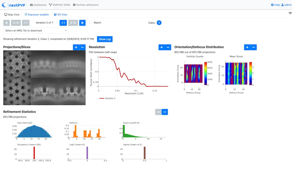
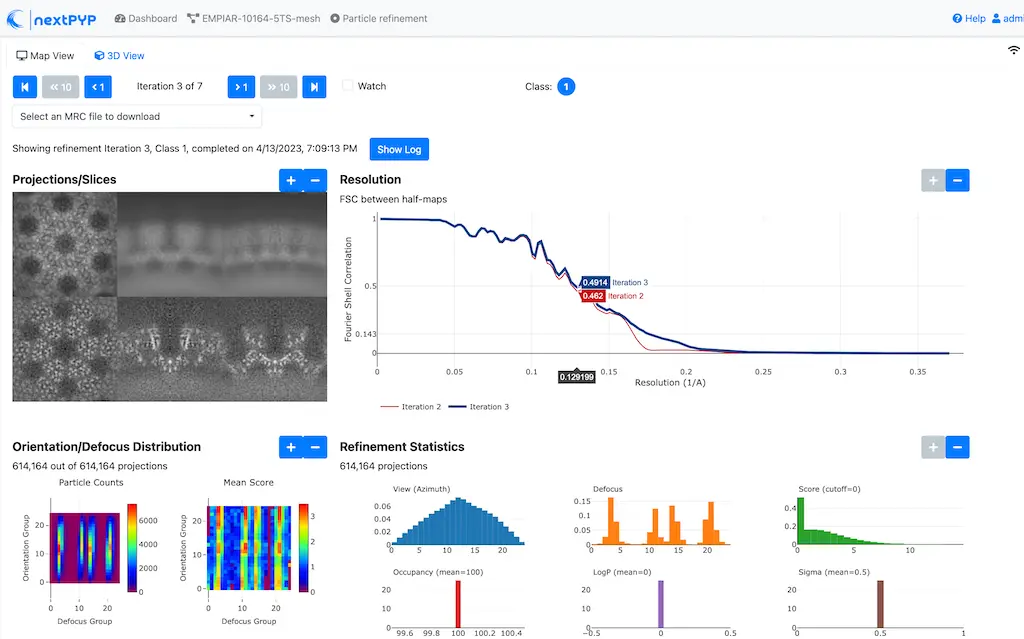
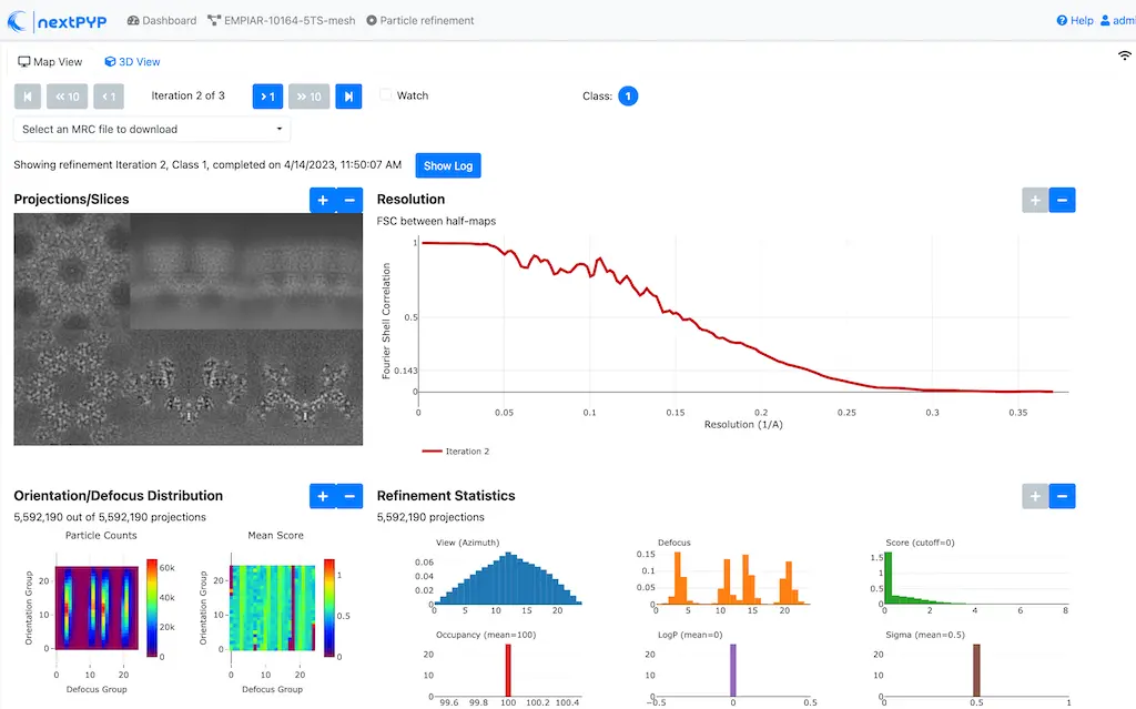
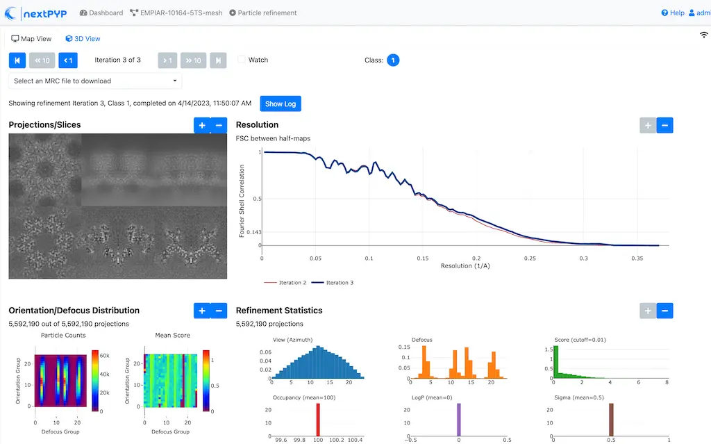
Click inside the 3D refinement block to inspect the results:
Tip
Use the navigation bar at the top left of the page to look at the results for different iterations
Step 9. Filter particles
Identify and remove duplicates and particles with low alignment scores ( 4 min)
Click on
Particles(output of the 3D refinement block) and select Particle filteringGo to the Particle filtering tab:
Specify the location of
Input parameter file (*.bz2)by clicking on the icon and selecting the file tomo-new-coarse-refinement-*_r01_04.bz2Set
Score thresholdto 2.5. This will remove particles with scores lower than 2.5 (scores measure the fit between particles and the 3D reconstruction)Set
Min distance between particles (unbinned pixels/voxels)to 10. This will remove duplicate particles that are closer than 10 pixels to each otherSet
Lowest tilt-angle (degrees)to -15. This will exclude projections below -15 degrees, as they contribute little high-resolution information to the reconstructionSet
Highest tilt-angle (degrees)to 15. This will exclude projections above 15 degrees, as they contribute little high-resolution information to the reconstructionCheck
Generate reconstruction after filtering. This will calculate a new reconstruction after filtering the particles to confirm that the filtering was successfulCheck
Permanently remove particles. This will remove the particles from the dataset after filtering to save space and reduce processing time
Click Save, Run, and Start Run for 1 block. You can see how many particles were left after filtering by looking at the job logs.
Step 10. Region-based local refinement (before masking)
Constraints of the tilt-geometry are applied over local regions ( 1 hr)
Click on
Particles(output of Particle filtering block) and select 3D refinementGo to the Sample tab:
Set
Particle radiusto 100Click on the Particle extraction tab
Set
Box size (pixels)to 384Set
Image binningto 1Click on the Particle scoring function tab
Set
Last tilt for refinementto 4. This will use the first five tilts for refinement (numbering is 0-based)Set
Max resolution (A)to 6:5Click on the Refinement tab
Select the location of the
Initial parameter file (*.bz2)by clicking on the icon and selecting the filetomo-fine-refinement-*_r02_clean.bz2Set
Last iterationto 3Set
Number of regionsto 8,8,2. This will divide the tomogram into 8x8x2 regions in x,y,z and refine the tilt-geometry parameters independently for each region
Click Save, Run, and Start Run for 1 block to run the job
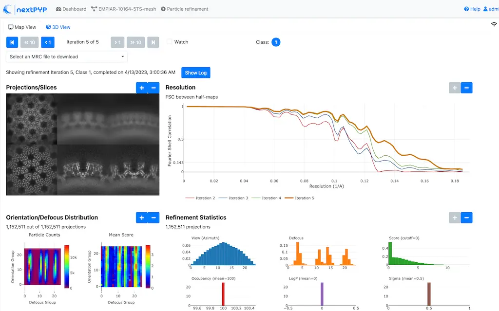
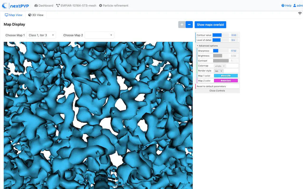
Click inside the 3D refinement block to inspect the results:
Step 11: Create shape mask
Use most recent reconstruction to create a shape mask ( <1 min)
Click on
Particles(output of the last 3D refinement block) and select MaskingGo to the Masking tab:
Select the
Input map (*.mrc)by click on the icon and selecting the file tomo-new-coarse-refinement-*_r01_03.mrcSet
Threshold for binarizationto 0.45. This value may be different for you. Use the 3D viewer to visualize the map and adjust the threshold value accordinglySet
Width of cosine edge (pixels)to 8. This will create a cosine edge of 8 pixels at the edges of the mask to avoid sharp transitions
Click Save, Run, and Start Run for 1 block to run the job
Click on the menu icon of the Masking block, select the Show Filesystem Location option, and Copy the location of the block in the filesystem (we will use this in the next step))
Click inside the Masking block to inspect the results of masking.
Note
A suitable binarization threshold should include the protein density while excluding the background. You may skip this step and use the pre-calculated mask provided with the raw data
Step 12: Region-based constrained refinement
Constraints of the tilt-geometry are applied over local regions ( 2 hr)
Click on
Particles(output of the last 3D refinement block) and select 3D refinementGo to the Particle scoring function tab:
Set
Max resolution (A)to 5:4:3.5Set
Masking strategyto from fileSpecify the location of the
Shape maskproduced in Step 11 by clicking on the icon , navigating to the location of the Masking block by copying the path we saved above, and selecting the file frealign/maps/mask.mrc (you may also use the pre-calculated mask provided with the raw data if you skipped the previous step)Click on the Refinement tab
Select the
Input parameter file (*.bz2)by click on the icon and selecting the file tomo-new-coarse-refinement-*_r01_03.bz2Set
Last iterationto 4
Click Save, Run, and Start Run for 1 block to run the job
Click inside the 3D refinement block to inspect the results:

Step 13: Particle-based CTF refinement
Per-particle CTF refinement using most recent reconstruction ( 3 hr)
Click on
Particles(output of the last 3D refinement block) and select 3D refinementGo to the Particle scoring function tab:
Set
Last tilt for refinementto 10Set
Max resolution (A)to 3.1Click on the Refinement tab
Select the
Input parameter file (*.bz2)by click on the icon and selecting the file tomo-new-coarse-refinement-*_r01_02.bz2Uncheck
Refine tilt-geometryto disable refinement of the tilt-geometry parametersUncheck
Refine particle alignmentsto disable refinement of particle posesCheck
Refine CTF per-particleto enable per-particle CTF refinement. While it’s possible to refine CTF parameters, tilt geometry, and particle poses simultaneously, this is not recommended, as it may increase the risk of overfitting.
Click Save, Run, and Start Run for 1 block
Click inside the 3D refinement block to inspect the results

Step 14: Movie frame refinement
Particle-based movie-frame alignment and data-driven exposure weighting ( 3 hr)
Click
Particles(output of the last 3D refinement block) and select Movie refinementGo to the Particle scoring function tab:
Set
Last tilt for refinementto 4Set
Max resolution (A)to 3.2Click on the Frame refinement tab
Specify the
Input parameter file (*.bz2)by clicking on the icon and selecting the file tomo-new-coarse-refinement-*_r01_02.bz2Set
Spatial sigma (unbinned pixels/voxels)to 200.0. This ensures that the motion trajectories of neighboring particles within a 200-pixel radius are correlated
Click Save, Run, and Start Run for 1 block
Click inside the Movie refinement block to inspect the results:
Step 15: Refinement after movie frame refinement
Additional refinement using new frame alignment parameters ( 1 hr)
Click
Frames(output of Movie refinement block) and select 3D refinement (after movies)Go to the Particle scoring function tab:
Set
Min number of tilts for refinementto 2Set
Max resolution (A)to 3.2Click on the Refinement tab
Specify the
Input parameter file (*.bz2)by clicking on the icon and selecting the file tomo-flexible-refinement-*_r01_02.bz2Check
Refine tilt-geometrySet
Tilt-angle range (degrees)andTilt-axis angle range (degrees)to 1.0Set
Tilt-axis position range (A)to 10.0Check
Refine particle alignmentsSet
Particle rotation Phi range (degrees),Particle rotation Psi range (degrees), andParticle rotation Theta range (degrees)to 1.0Set
Particle translation range (A)to 10.0
Click Save, Run, and Start Run for 1 block
Click inside the 3D refinement (after movies) block to inspect the results:
Step 16: Map sharpening
Apply B-factor weighting in frequency space ( <1 min)
Click
Frames(output of 3D refinement (after movies) block) and select Post-processingGo to the Post-processing tab:
Specify the
First half mapby clicking on the icon and selecting the file tomo-flexible-refinement-*_r01_half1.mrc (output of the 3D refinement (after movies) block)Set
Threshold valueto 0.35. This value will be used to calculate the shape mask for the map. The threshold value should be adjusted to include the protein density while excluding the backgroundSet
B-factor methodto adhoc. This will allow us to set the B-factor value manuallySet
Adhoc value (A^2)to -25. This value may vary for you—more negative values will apply stronger sharpening. Use the 3D viewer to visualize the map and adjust the B-factor value as needed
Click Save, Run, and Start Run for 1 block
You can inspect the result by clicking inside the Post-processing block:
Info
Running times were measured running all tilt-series in parallel on nodes with 124 vCPUs, 720GB RAM, and 3TB of local SSDs